Controller Testing – Simulating Actuators with Multi-Channel Electronic Loads
The test setup can simulate a large number of actuators simultaneously and independently of one another. In such setups, the load profiles of components such as lighting, windshield wipers, door actuators, power steering, brake assist, pumps, cooling fans, and heating elements are electrically simulated. This allows the controller to be validated in a realistic yet controlled environment.
A test setup for central vehicle controllers uses multiple channels of scalable electronic loads. The type of load we choose depends on the VCU/ECU architecture and the specific actuator that the load will simulate.
The power consumption of these components varies widely. At the lower end are small power consumers such as LED lighting and climate control valves, which use less than 15 watts. In the mid-range, we find components such as windshield wipers, power windows, and camera systems that consume between 15 and 100 watts. The real power hogs include the rear window defroster, cooling fans, ABS, and EPS. These can easily draw 200 to as much as 1,000 watts.
When designing the test system, however, we must look beyond these normal consumption figures. This is because electric motors experience a very high inrush current when starting up or in the event of a mechanical blockage. This current spike can easily be five to six times higher than normal. It is crucial for the test system that the programmable DC loads can precisely simulate these rapid, intense spikes. This allows us to reliably verify that the smart fuses (eFuses) and MOSFETs on the VCU respond correctly and do not trip unnecessarily.”
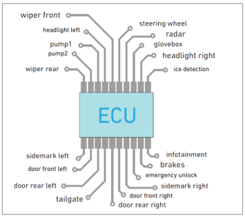
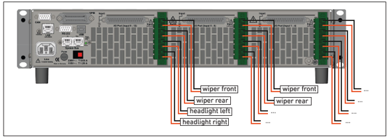
A modular, multi-channel load solution is used, built around multiple systems, each with a master-slave architecture. A single system consists of a master unit with a user interface and data communication capabilities, supplemented by multiple slave units that together provide dozens of independent load channels. By combining multiple such systems, the test setup can even be scaled up to hundreds of channels. This is essential for testing modern zonal architectures in which a single controller manages a large number of I/O signals.
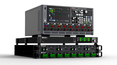
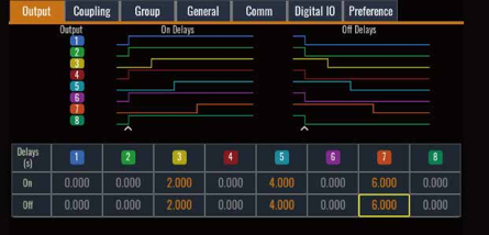
Each individual channel within the electronic load is programmable and can simulate various load modes, such as constant current (CC), constant voltage (CV), constant resistance (CR), and constant power (CP). Depending on the configuration, channels can cover a wide range of voltages and currents, allowing for the realistic simulation of a variety of actuators—from low-power devices such as lighting to more demanding components such as motors or pumps.
A key feature of this setup is the ability to generate dynamic load profiles. This allows not only static loads to be simulated, but also time-dependent behavior such as inrush currents, PWM response, and variable load conditions. This is crucial for validating the output control of ECUs and VCUs, as well as for testing diagnostic functions such as fault detection in the event of an open load, short circuit, or overload.
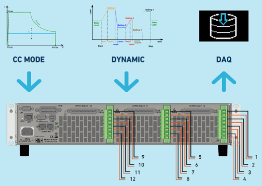
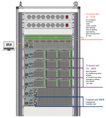
In addition, such systems support extensive automation through standardized interfaces and programming protocols, such as SCPI. This makes it possible to define, repeat, and integrate complex test scenarios into automated test environments. Features such as trigger mechanisms, internal data logging, and analog measurement outputs for voltage and current contribute to a detailed analysis of system behavior during testing.
The scalability and flexibility of multi-channel load setups make them particularly well-suited for testing modern vehicle architectures, including zonal ECU systems and integrated controllers. By simultaneously emulating a large number of actuators, the controller’s behavior can be evaluated under realistic load conditions, which is essential for thorough verification and validation prior to integration into the vehicle.
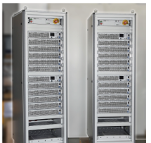
An H&H 4×72-channel setup with PMLA loads
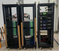
33-channel ITECH IT2700 test tower with 500W regenerative load modules
Read more on the pages below:
– ECU and VCU Controllers
– The difference between the two and the shift toward scalable solutions

