Anti-Islanding Test Requirements and Procedures
The requirement for such a test setup is to generate an islanding condition in which the DUT (inverter) must disconnect within the specified time limits. This disconnection time is measured from the moment the switch is opened to isolate the grid, until the moment the DUT stops supplying current to the grid.
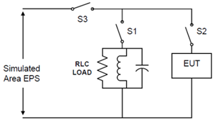
In parallel with the DUT, a load must be connected in accordance with the IEC‑62116 standard to ensure a balanced load condition. This load (RLC circuit) must have a Q‑factor of 1, ensuring that the output current flowing through the switch (S3) to the grid remains within 2% of the maximum output current.
In addition to testing the balanced load condition at Q = 1.0, the test must be repeated with the reactive load (capacitive or inductive) adjusted in 1% increments over the range of 95% to 105% of the initial balanced load component value. If the DUT’s trip times continue to increase at the 95% or 105% points, additional 1% steps are taken until the trip times begin to decrease.
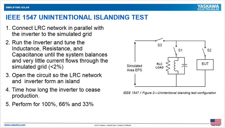
A typical anti‑islanding test setup is designed to evaluate whether a grid‑connected inverter or distributed energy resource (DER) can reliably detect a condition that results in islanding — an event known as unintended islanding.
Typical Anti‑Islanding Test Configuration
- AC Grid simulator
- The device under test (DUT)
- Adjustable RLC load bank
- Measurement equipment (timing)
Read more on the pages below:

