Testing Electric Ship Propulsion
5.1 Battery Emulation
A battery essentially functions as a DC power supply/load but with specific characteristics. Each battery has an internal resistance, and its output voltage depends on its state of charge. Other variables also influence performance, such as the number of charge cycles, which affects capacity. Standard DC power supplies / DC Loads or bidirectional power supplies cannot accurately simulate these properties, which is why battery emulation software is used.
Why emulate a battery?
One key reason is the repeatable configuration that always delivers the same values—essential for quality control.
Large batteries are often heavy and cumbersome, while emulation allows for easy adjustment of voltage, current, capacity, and charge status. Want to test at 90%, then 10%, then 50%? With emulation, this takes seconds—real batteries require charging/discharging.
Another major advantage is safety. Insurers prefer avoiding real batteries when possible due to fire risks. Ships are often tested with battery emulators, with actual batteries installed just before commissioning.
Battery Emulation Software
The Itech BSS2000 software offers a user-friendly tool for battery emulation across various applications. The basic version supports Li-ion and lead-acid batteries, allowing users to program battery curves using standard values or import charge/discharge profiles via CSV files. SOC adjustments are quick and simple
With the BBS2000 Pro version, you get even more functionality with almost all battery types pre-programmed as standard. In addition, importing Matlab files is also possible and even the BMS can be simulated so that battery simulation is possible for various applications. Of course, the software also provides protection for you battery with various settings.
For detailed specifications, refer to the BSS2000 datasheet. Compatible Itech power supplies include: IT6000B, IT6000C, IT-M3400, IT-M3600, IT-M3900B, IT-M3900C, and IT6600C.

5.2 Testing a Battery Pack
To test a battery pack, we can perform the following tests:
– Determining the impedance of the complete battery pack
– Determining the capacity of the battery pack
– The number of charge/discharge cycles
When testing battery packs, we are dealing with high power ratings (kWh), higher currents and also high voltages.
Determining the impedance
The internal resistance of a battery pack can be determined quite simply by means of a step response measurement in the battery load. Battery packs require a relatively heavy load for this. Bi-directional DC power supplies that can handle these voltages and currents well, such as the IT6000C/D and IT6600C/D, are suitable for this purpose.

Determining the capacity of the battery pack
It is important to draw up a clear script setting out the conditions under which the battery capacity is determined.
- What is the maximum charging voltage?
- To what voltage can the battery be discharged?
- What is the discharge current or discharge current cycles?
- At what temperature does it discharge and charge?
- With what charging current is the battery recharged as well?
And are these values in line with your application of this battery? A battery used in a buoy at sea has a completely different ambient temperature and charge/discharge cycle than a battery used in, for example, an inland vessel. Depending on the voltage and capacity of the battery pack, bidirectional DC power supplies are often used for testing in this case. At high power levels, we see the advantages of using regenerative bidirectional DC power supplies.
For small packs, the TTMS product portfolio includes two quadrant DC power supplies in the voltage range from 0-80V to 0-1500V with power ratings from 200W to 18kW. These power supplies are fully tailored to these applications and offer the option of an autonomous charge and discharge cycle with the parameters specified by the customer. Charging or discharging can be performed based on set values such as charge/discharge voltage, current and time. In addition, we have stop values for charging and discharging in the form of stop voltage, stop current and stop capacity. With a single bi-directional DC power supply, it is also possible to connect a temperature sensor so that the temperature of the battery can also be a stop value.
With most bidirectional DC power supplies, we can build a test system by placing a number of units in a master/slave configuration to create configurations of up to several MW. We are already seeing 6 MW charging stations on ships.
The number of charge/discharge cycles of a battery pack
These tests can be performed on the entire pack. However, this is usually limited to the battery module, as these tests are lengthy and costly. The same hardware can be used for the tests as for the capacity test, often supplemented with comprehensive battery test software.
5.3 Testing charging solutions for ships
There are various charging solutions for hybrid and fully electric ships. These solutions range from autonomous telescopic charging with a loading crane to arm loading systems and manual charging stations. With capacities of up to 6 MW and even more. The manual fast charging stations can be equipped with CCS2 plugs, which can be used to charge both alternating current and direct current.
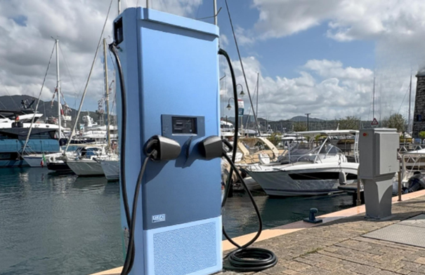
Manual charging station on the quay.
The use of AC sources and grid emulators, such as the Itech IT7800 and IT7900 series, enables manufacturers of charging solutions to simulate realistic grid conditions (such as voltage dips, harmonics or grid frequency variations) and test their systems as they function in practice.
5.4 Testing DC/DC converters
DC/DC converters are used to convert the high DC voltage of the DC electrical system to a lower voltage. This lower voltage is required, for example, to power navigation and communication systems.
An additional task of the DC/DC converter is to charge the 24V battery in the vessel. Although this lead or lithium battery is much smaller than the high-voltage package, it remains an important source of energy, especially for activating safety systems and temporarily bridging peak loads or faults in the high-voltage circuit.
Testing DC/DC converters
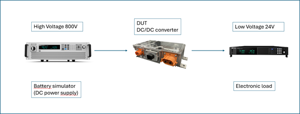
The converter that is central to the above test setup (Device Under Test) is connected to both a high-voltage side and a low-voltage side, with both sides being powered and measured by programmable power supplies.
On the high-voltage side, the DC/DC converter is powered by a battery simulator that supplies a voltage level of, for example, 800 volts, depending on the type of converter being tested. On the low-voltage side, one or more DC consumers (DC electronic loads) are connected that simulate the vessel’s 24-volt on-board systems.
The setup makes it possible to analyse the behaviour of the DC/DC converter under various voltage and current conditions, such as during start-up, under variable load, or during voltage fluctuations. The efficiency, temperature behaviour and stability of the output voltage can also be accurately evaluated.
TTMS has various DC power supplies, battery emulators and DC loads from H&H and Itech, among others, in its product portfolio. Itech DC power supplies: IT6000C/D and IT6600C/D. Itech DC electronic load IT-M3300.
5.5 Testing DC/AC inverters
DC/AC inverters are used to convert the high-voltage DC electrical system into a 240V AC electrical network on board. This provides electricity to the lighting and living areas on board, among other things.
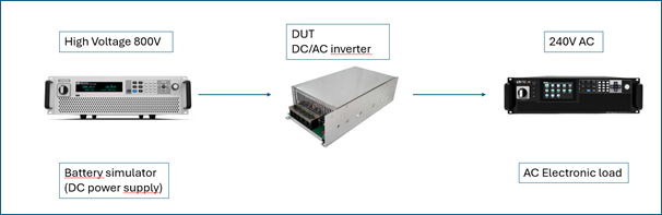
Testing DC/AC inverters.
The inverter at the heart of the above test setup (Device Under Test) is connected on the DC side to a DC programmable power supply and on the 240 AC side to an AC programmable electronic load.
On the DC side, the DC/AC converter is powered by a DC power supply that delivers a voltage level of, for example, 800 volts, depending on the type of converter being tested. On the AC voltage side, one or more AC consumers (AC electronic loads) are connected that simulate the vessel’s 240-volt AC systems.
The setup makes it possible to analyse the behaviour of the DC/AC inverter under various voltage and current conditions, such as during start-up, under variable load, or during voltage fluctuations. The efficiency, temperature behaviour and stability of the output voltage can also be accurately evaluated.
TTMS has various DC power supplies and AC loads from H&H and Itech, among others, in its product portfolio. Itech DC power supplies: IT6000C/D and IT6600C/D. Itech electronic loads: IT8200 and IT8200E.
For more information, please refer to the sections below.
1. Introduction to developments within the maritime industry
2. Electrically powered systems in the maritime industry
3. Standards and guidelines
4. Electric ship propulsion