Testing EV parts and components
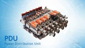
6.1 What is a PDU?
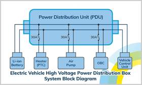
In an electric vehicle (EV), the Power Distribution Unit (PDU) plays a central role within the electrical architecture. The PDU acts as the electrical distribution centre that distributes the high-voltage energy from the traction battery (typically 400V or 800V) to various subsystems in the vehicle. These consumers include the traction inverter, the DC/DC converters, the on-board charger, the HVAC system (air conditioning and heating) and other high-voltage components such as electric compressors or heating modules.
In addition to distributing electrical energy, the PDU also performs a protective function. It contains safety elements such as fuses, relays, or solid-state switches, which protect the system against overcurrent, short circuits, and other electrical faults. Modern PDUs are often equipped with measurement and communication functions, allowing parameters such as voltage, current, temperature, and fault conditions to be continuously monitored. This data is transmitted to the vehicle control unit (VCU), which uses it to control the entire electrical system safely and efficiently.
Depending on the vehicle architecture, the PDU may be centrally located near the high-voltage battery, or there may be multiple distributed PDUs supplying power to local subsystems. In some cases, functions such as DC/DC conversion, precharge circuits, or isolation monitoring are also integrated directly into the PDU to save space and weight.
The Power Distribution Unit is a critical link in the operation and safety of an electric vehicle. The main electrical components of a PDU are: relays, fuses, connectors, copper busbars, current measurement systems, voltage measurement systems, precharge resistors, and wiring harnesses.
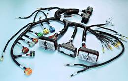
6.2 Testing high-voltage cable harnesses or wiring harnesses
The high-voltage cable harness in electric vehicles plays an essential role in energy distribution within the high-voltage system. It consists of connectors, terminals, conductors, insulation material, and other components, and provides the electrical connection between components such as the traction battery, AC and DC charging ports, maintenance switches, air conditioning modules, electric powertrain, and electric motors.
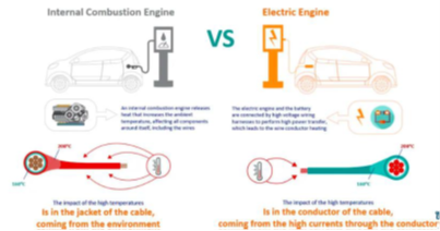
Due to the high voltages and currents with which these cables operate, combined with their larger wire diameters and often high number of cables, the design poses significant technical challenges. These include complex cable routing, safety requirements, shielding against electromagnetic interference, as well as weight and cost efficiency.
High-voltage cables in electric vehicles differ significantly from traditional automotive cables. Whereas conventional systems are often designed for 12V or 24V, the cabling in electric vehicles must generally be suitable for a nominal voltage of 600 volts. In commercial vehicles or buses, this rises to 1000 volts and in the latest electric trucks even to 1500 volts. There are also higher standards in terms of temperature requirements. Cables located in the passenger compartment or engine compartment often have to withstand temperatures of 105 degrees Celsius or more, with cables for electric vehicles often requiring a temperature resistance of 125 to 150 degrees Celsius.
Finally, these cables are expected to have a longer service life. Whereas conventional automotive cables are often designed for approximately 3,000 operating hours, high-voltage cables in electric vehicles can have an expected service life of more than 12,000 hours, depending on the application, provided that the ambient temperature and loads remain within specification.
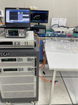
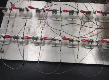
A practical test case for a cable harness that needs to be tested. In the test setup, a temperature rise test is performed with a current of more than 1000 A. By repeatedly increasing or decreasing the input current and observing the changes in the output current and temperature, it can be assessed whether the connector is suitable for use in electric vehicles.
A test setup that supports both AC and DC tests is used for the temperature rise test of high-voltage cable harnesses. Examples of test configurations include: DC 1000 V at 800 A (up to 400 kW), AC 700 V at 800 A, and high-voltage tests up to 1200 V in combination with low current for high measurement accuracy.
6.3 Pre-charge relais test
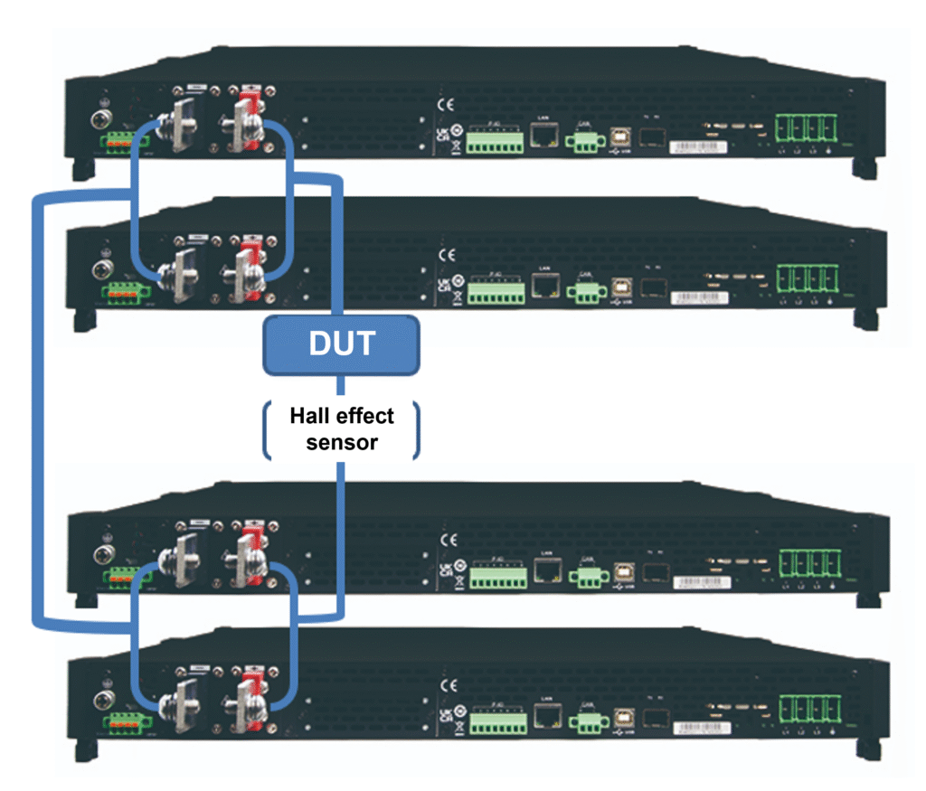
For this, we need a bidirectional DC power supply with a low voltage but with the ability to deliver very high currents. In our practical test setup, we used two sets of multiple IT-M3900C 10V DC bidirectional power supplies connected in parallel. Switching the current direction is achieved by setting the voltage value, which allows the bidirectional operation to be simulated.
When testing the relays in the precharge path, customers require a bidirectional DC power supply with a voltage of 10 V and a current of 1500 A.
The setup allows for quick switching between positive and negative current, enabling both fast and slow load conditions to be simulated.
Based on preset tables with up to 100,000 different current values, the test setup can run continuously for several days.
6.4 High-voltage MSD connector test
The manual service disconnect (MSD) is a high-voltage connector with an integrated fuse. To ensure the safety of people and vehicles during maintenance work on electric vehicles, the power supply to the high-voltage system is interrupted by disconnecting the MSD. This provides electrical isolation of the high-voltage system and also offers protection against short circuits.
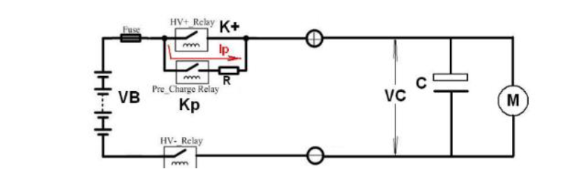
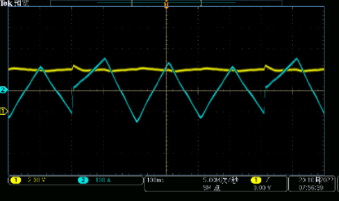
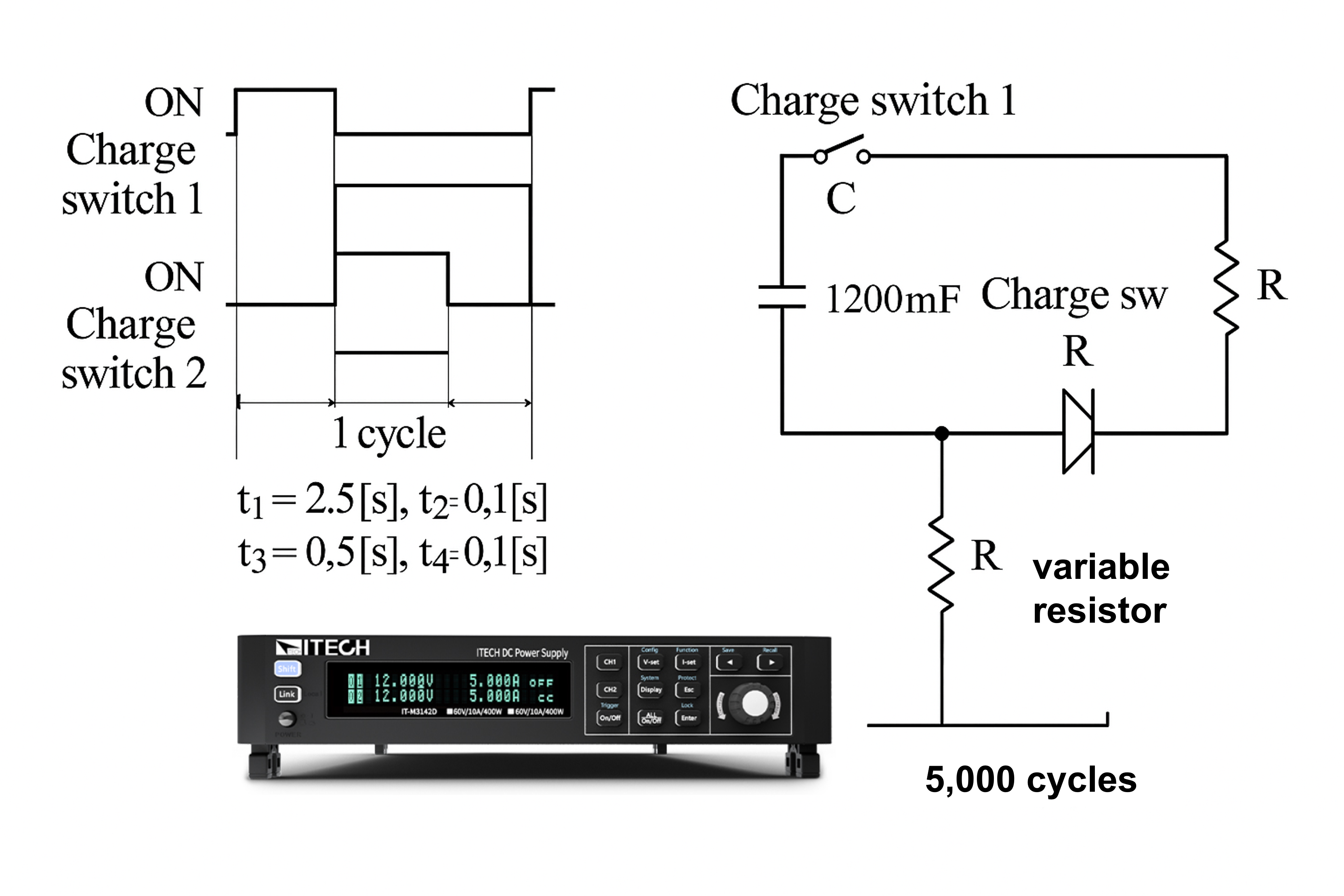
The correct functioning of the MSD can be tested with a cyclic current pulse test.
A DC power supply and a test setup with a capacitor, switches, and a variable resistor are used to determine the discharge current. The discharge cycle is repeated up to 50,000 times to ensure the correct functioning of the MSD.
6.5 Testing the fuse
In an electric vehicle, fuses play an essential role in protecting both the electrical systems and the occupants. They act as passive safety devices that interrupt the circuit when an overload or short circuit occurs. In this way, they prevent damage to components or the creation of dangerous situations.
Because electric vehicles use high voltages, typically up to 800 volts and, in some applications, very high currents, specially designed high-voltage fuses are used. These are capable of responding quickly and reliably to fault conditions, even under heavy electrical loads.
Fuses in EVs are used in the main circuits of the traction battery pack, in DC charging circuits, in DC/DC converters, within the electric drive and in heating or air conditioning systems, among other places. They must not only meet the correct nominal current and voltage values, but also be able to withstand high ambient temperatures, vibrations and thermal cycles as found in automotive applications.
Modern vehicles often use fast-acting fuses specifically designed for high DC voltages. In some cases, fuses are integrated into other components, such as the manual service switch (MSD) or battery management systems, to save space and further enhance safety.
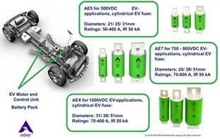
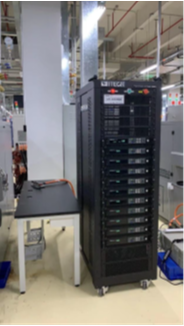
ADLER fuses for EVs 10V/5000A test tower for fuses
A high-power bidirectional DC test setup is required to check the critical parameters. It is essential to accurately simulate operating conditions at high frequencies, for example with a 10 ms load cycle and a measurement interval of 10 ms. In addition, an extremely fast rise and fall time of only 10 ms is required. Finally, extremely high currents are often required, with demands of up to 5000 A and higher.
6.5 Electric power steering (EPS)
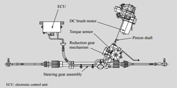
Electric power steering (EPS) is a power steering system that uses an electric motor to provide additional steering torque. Compared to the traditional hydraulic power steering system (HPS), EPS offers several advantages. The system mainly consists of a torque sensor, a vehicle speed sensor, an electric motor, a reduction mechanism, and an electronic control unit (ECU).
The basic principle of EPS works as follows: the torque sensor is connected to the steering rod (gear shaft). When the driver turns the steering wheel, the sensor detects the torque and, under the influence of the torsion bar, a relative angular displacement occurs between the input and output shafts. This displacement is converted into an electrical signal and transmitted to the ECU. Based on the signals from the torque sensor and the vehicle speed sensor, the ECU determines both the direction of rotation of the motor and the amount of electrical assistance.
This system allows the system to adjust the degree of power steering in real time to match the driving speed. At low speeds, the steering feels light and smooth, while at higher speeds, the steering feels more stable and reliable.
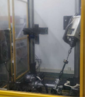
800W EPS drive
Manufacturers must simulate and test the power steering system. The rotation of the steering wheel is simulated on a test bench. This helps to verify the relationship between the rotational movement and the motor output as accurately as possible using the torque sensor and pressure sensors on both sides of the force measurement. Automatic durability tests are also carried out. At the same time, the test setup supplies the system with a 13.5 V power supply for driving the electric motor. CAN communication is used to collect steering system parameters and data from the surrounding sensors in real time for statistical comparison.
Since the car must be able to steer both left and right, the electric motor alternately rotates forwards and backwards. Just before the motor changes direction, the inertia of the rotor generates a counter-EMF (electromotive force). For the power supply, the voltage direction remains the same, but the current reverses: from positive output to positive inflow.
This test requires a bidirectional DC source as part of the test setup for electronic power steering systems.
For further information about the testing equipment to be used, please contact us.