EV DC/DC Converters and Traction Inverter
3.1 Overview of AC-DC, DC-DC and DC-AC converters
In addition to the On-Board Charger (OBC), an electric vehicle (EV) contains various types of converters, each of which performs a specific function within the vehicle’s energy management and drive system. One of the most important converters is the traction converter (or inverter for the powertrain). This converts the direct current (DC) from the battery pack into alternating current (AC) to drive the electric motor(s). Depending on the type of motor – such as a three-phase induction motor or a permanent magnet synchronous motor – this converter generates a precise, variable AC voltage and frequency to control the torque and speed of the motor.
In addition, there is the DC/DC converter, which converts the high voltage of the traction battery system (e.g. 400 V or 800 V) to a lower voltage (often 12 V or 48 V) to power the conventional electrical systems in the car, such as lighting, infotainment, air conditioning and ECUs. In modern EVs, this converter can also be bi-directional, allowing the 12V battery to be recharged by the high-voltage battery in emergencies.
Furthermore, some EVs may still have auxiliary converters, for example to control electrical auxiliary components such as electric air conditioning compressors, electric power steering or active chassis components. These systems often require specific voltage levels and are powered by special converters that are precisely matched to their load.
In high-performance or advanced EVs, especially those with multiple drive units (such as four-wheel drive with independent front and rear axles), there are often multiple traction inverters – one per motor – to enable precise torque vectoring. Each of these inverters functions independently but communicates with the central control unit to ensure optimum driving dynamics.
3.2 Testing the traction converter AC-DC and DC-AC
The traction converter, also known as the drive inverter, is a crucial component in an electric vehicle (EV), as it is responsible for directly controlling the electric motor(s). The battery of an EV supplies direct current (DC), while most traction motors require alternating current (AC) to function properly. The task of the traction converter is therefore to efficiently convert this DC energy into a precisely controlled AC voltage and frequency, tailored to the driving conditions and the required motor performance.
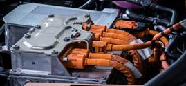
The inverter usually consists of three main components: a power electronics section, a control or management module, and a cooling system.
- The power section contains semiconductor components such as IGBTs (Insulated Gate Bipolar Transistors) or, increasingly, SiC MOSFETs (Silicon Carbide Metal-Oxide-Semiconductor Field-Effect Transistors), which enable high currents to be switched at high speed with minimal losses.
- The control electronics determine how these circuits operate and thereby regulate the torque, speed and direction of rotation of the motor. Advanced control algorithms (such as vector control or direct torque control) ensure that the motor runs smoothly, powerfully and efficiently.
- Because switching generates heat, an efficient cooling system (usually liquid-cooled) is essential to prevent overheating and ensure the longevity of the components.
The traction inverter also plays a role in regenerative braking. Here, the function is reversed: the electric motor temporarily acts as a generator and converts kinetic energy into electrical energy, which is then stored in the high-voltage battery via the inverter.
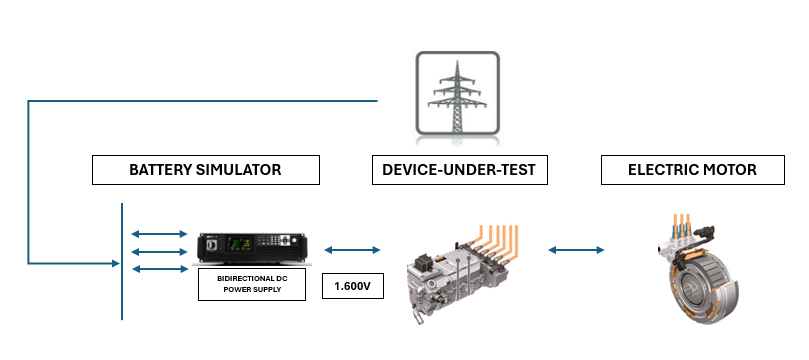
The traction controller is tested under controlled conditions, without the need for a real traction battery or vehicle. On the left-hand side of the setup is a battery simulator, such as an ITECH IT6000C, which supplies a stable high-voltage direct current – in this example 800 volts – to simulate the vehicle’s battery.
The inverter converts this DC voltage into a precisely regulated AC voltage, which is used to control the electric drive motor. During the test, a real electric motor is connected, or sometimes a motor emulator, so that the behaviour of the inverter can be realistically assessed under different load conditions.
This configuration makes it possible to analyse the operation of the inverter at different voltage levels and load conditions, including testing power losses, temperature behaviour, and the performance of the motor control algorithms. Regenerative braking can also be simulated, whereby the inverter feeds energy back to the battery simulator. It is important to use a regenerative bi-directional DC source that can also absorb energy and feed it back into the grid.
3.3 Testing DC/DC converters
The DC/DC converters in an electric vehicle (EV) are an essential component that forms the connection between the high-voltage system of the battery pack and the traditional low-voltage electrical system of the car. Whereas the battery system typically supplies voltages of 400 volts or even 800 volts in modern EVs, many conventional vehicle systems – such as lighting, infotainment, sensors, air conditioning control, windscreen wipers and control units (ECUs) – still operate at 12 and 24 volts (or in some cases 48 volts). The DC/DC converter ensures that these systems are powered safely and reliably.
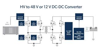
This converter is essentially an electronic voltage converter that converts direct current at a higher voltage to direct current at a lower voltage, with high efficiency and precise control. Inside the DC/DC converter, there is usually a combination of switches (such as MOSFETs), a transformer or coil for energy transfer, and a control circuit that continuously monitors and adjusts the output voltage and current.
An additional task of the DC/DC converter is to charge the 12V battery in the vehicle. Although this lead or lithium battery is much smaller than the high-voltage pack, it remains an important source of energy, especially for starting the vehicle, activating safety systems, and temporarily bridging peak loads or faults in the high-voltage circuit. In this sense, the DC/DC converter fulfils a similar function to the alternator in a combustion engine vehicle.
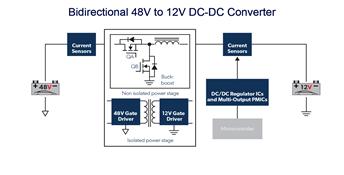
In modern EV architectures, the converter can be bidirectional, which means that energy can be converted not only from high to low, but also vice versa in specific situations – for example, to support the traction battery via an external charger at 12V level, or for diagnostic purposes.
Depending on the vehicle, there may also be multiple DC/DC converters, for example one for the 12V system and one for a 48V system (for heavier electrical auxiliary systems such as active stabilisation or air suspension). In some cases, the converter is integrated into other components, such as the OBC or the traction inverter, to save space, weight and costs.
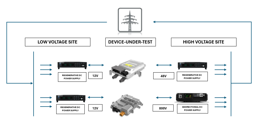
This test setup is intended for testing DC/DC converters used in electric vehicles to convert high voltage to lower voltage, or vice versa. The converter at the centre of this setup (Device Under Test) is connected to both a high-voltage side and a low-voltage side, with both sides being powered and measured by programmable power electronics.
On the high-voltage side, the DC/DC converter is powered by a battery simulator that supplies a voltage level of, for example, 800 volts or 48 volts, depending on the type of converter being tested. On the low-voltage side, one or more DC sources are connected that represent the vehicle’s 12-volt on-board systems. These simulators can function both as a load (to measure the current output of the converter) and as a voltage source in bidirectional tests.
The setup makes it possible to analyse the behaviour of the DC/DC converter under various voltage and current conditions, such as during start-up, under variable load, or during voltage fluctuations. The efficiency, temperature behaviour and stability of the output voltage can also be accurately evaluated. If the converter is bidirectional, it is also possible to test how it feeds energy back to the high-voltage side. For this, we need a bidirectional and regenerative DC source.
For an overview of the bi-directional power supplies/battery simulators within the TTMS product portfolio from suppliers H&H, NF Corp, Itech, and Cinergia, please refer to our overview page.