EV Battery Pack Testing
Testing a battery pack is, of course, an extension of testing a battery module.
Here too, we can perform the following tests:
– Determining the impedance of the complete battery pack
– Determining the capacity of the battery pack
– The number of charge/discharge cycles
Compared to testing battery modules, we are dealing with higher power ratings (kWh), higher currents and, increasingly, higher voltages. This in itself presents new challenges. We are currently seeing battery packs for buses and lorries with voltages of up to around 800V. However, developments are already moving towards 1000 and 1250V battery packs.
The biggest challenge, however, lies in the charging currents. With the aid of a pantograph, we can charge with fairly high currents. But electric lorries do not yet have pantographs. The challenge lies in cooled charging connectors, so that we still have a manageable cable that can handle high charging currents. And when we hear about the plans for the future, particularly for long-distance lorries, we are looking at charging currents of 2000A and more at a charging voltage of up to 1500V. There are still some challenges to be overcome.
Determining the battery pack impedance
Inherent to the structure of the battery cell, we are dealing with a certain resistance and parallel capacity of the materials used. In a battery module or pack, we are dealing with a series and parallel connection of battery cells, resulting in a certain impedance. Naturally, we want to keep the resistance as low as possible in order to minimise internal losses and battery heating. In addition to resistance, capacity also plays a role in dynamic loads. Below is a diagram showing how we can represent a battery cell electronically.
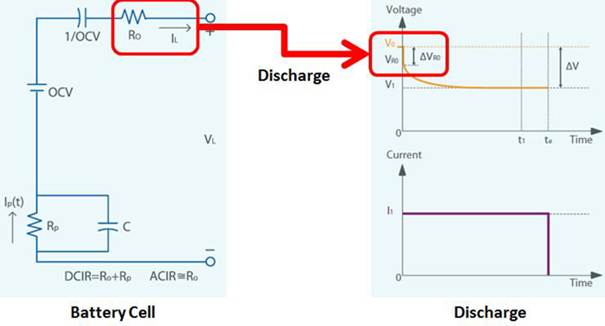
We can determine the internal resistance quite simply by means of a step response measurement in the battery load. This load variation produces an initial voltage variation, and when we divide that voltage variation by the current, we obtain the internal resistance. The internal resistance measurement for batteries is also laid down in various standards, such as DIN EN 61951 and DIN EN 61960. This method uses two different load currents to calculate the Ri. A number of manufacturers of electronic DC loads have integrated this as a standard measurement in the DC load, including Hoëcherl&Hackl with the H&H PLI series. We can therefore also use this method for a battery module or battery pack.
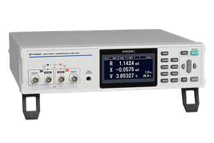
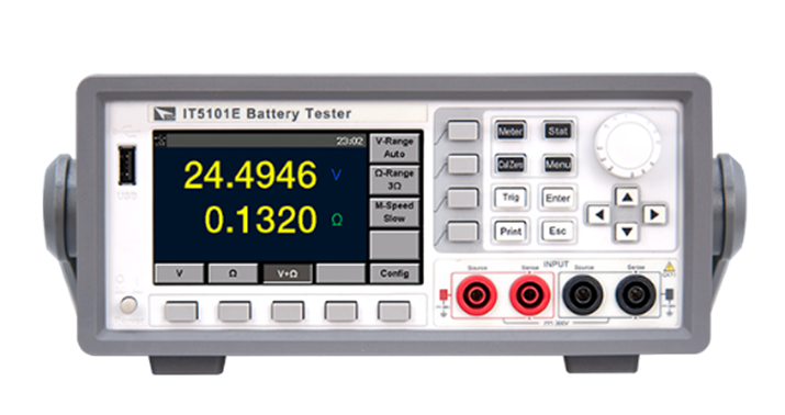
Internal capacity is also important for dynamic loads. This measurement is performed at a specific frequency (usually 1kHz) or across a wide range of frequencies in order to better determine the dynamic behaviour of the battery. With a battery module or pack, you need to take into account relatively high voltages with still relatively low impedance. Specific instrumentation is therefore required to perform these measurements with results in the micro- and milli-ohms range. For possible solutions, see, for example, the Itech IT-5100 series or the Hioki BT4560.
Determining the capacity of a battery pack
Determining the capacity of a battery pack depends on a large number of variables:
- Maximum charging voltage
- Maximum discharge voltage
- Maximum charging current
- Maximum discharge current
- Battery temperature
- Desired number of charge/discharge cycles
And some of these variables are contradictory values. You want to charge to the highest possible voltage and discharge to the lowest possible voltage in order to get maximum capacity from the battery. However, this comes at the expense of the battery’s lifespan or the number of charge/discharge cycles.
At low temperatures, capacity is lower, but this is also the case at excessively high temperatures.
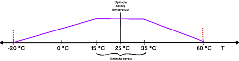
As you can see, different parameters are possible for ideal battery cell behaviour in different temperature conditions. Many of these parameters are also included in a good Battery Management System (BMS) for the optimal capacity/lifespan mix, depending entirely on the application for which the battery will be used.
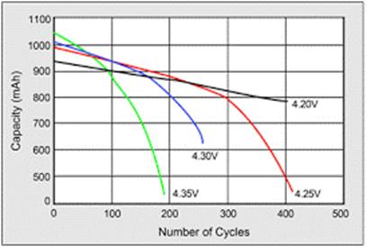
Charging with too high a charging voltage will shorten the battery’s service life. The number of charging cycles will decrease. In this example, we see 3.7V li-ion cells.
When discharging the battery, the optimum discharge voltage must also be taken into account to ensure maximum service life. If you discharge the battery too much (too low a voltage), its service life will be significantly reduced. A reduction of 20% in voltage is considered the maximum for a good service life.
There are therefore many parameters that need to be established before determining the optimal capacity of a battery pack. These parameters are usually provided by the battery manufacturer. However, as a user, you may want to test the battery under different conditions.
The same conditions that we mentioned when testing a battery module also apply when determining the capacity of a battery pack, except that higher power levels are now involved. Especially at these high power levels, we see the advantages of using (regenerative) bidirectional DC power supplies.
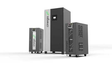
For small packs, the TTMS product portfolio includes two quadrant DC power supplies in the voltage range from 0-80V to 0-1500V with power ratings from 5kW to 42kW. These power supplies are fully tailored to these applications and offer the option of an autonomous charge and discharge cycle with the parameters specified by the customer. Charging or discharging can be performed based on set values such as charge/discharge voltage, current and time. This can also be done with a dynamic charge and discharge current. In addition, we have the stop values for charging and discharging in the form of stop voltage, stop current and stop capacity. With a single bi-directional DC power supply, it is also possible to connect a temperature sensor so that the temperature of the battery pack is also included in the results and can also be a stop value.
However, chargers for cars already have capacities of 11 and 22kW or even 44kW. DC chargers for lorries and buses already have capacities of up to 600kW and 900kW. However, we expect the first 1200kW chargers to be on the market soon. For boats, we have already seen a charging station with a capacity of 6MW.
With most bidirectional DC power supplies, we can build a test system by placing a number of units in a master/slave configuration to create configurations up to the MW range.
However, we also offer solutions with bidirectional DC power supplies of 60kW (max. 300kW) and a modular system with 15kW to 160kW modules that can be combined to create installations of >1.2MW with a maximum voltage of 1500V. The latest developments go even further in the form of 42kW modules in a 3U high mainframe, which allows us to create a 10MW system with a maximum voltage of 2250V and even 4500V.
The service life/charge and discharge cycle test
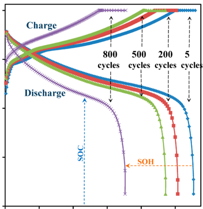
In this test, we assume a certain battery capacity at a certain temperature, at a certain charging voltage, at a certain maximum discharge voltage and at a certain discharge current (not dynamic), which is then referred to as 100% capacity. You then discharge this battery cell from a certain percentage and recharge it. If you do this often enough, depending on your pack, you will get a graph similar to the one below:
The number of charge/discharge cycles of a battery pack
If these tests are already performed on the entire pack (usually this is limited to the battery module), they are lengthy and costly. The same hardware can of course be used for the tests as for the capacity test, often supplemented with comprehensive battery test software.
With the Itech IT6642C bidirectional power supplies and multi-channel test software, we can even test up to 256 packs of MW units.